

Here is a short video of one of my students demonstrating the functionality of the setup.
The tutorial here shows you the configurations for the simulation in Packet Tracer. NOTE: Simulated network in PT works fine for most of the configs however it is not guaranteed everything will work well in actual hardware as IOS and config commands may vary. You may have different IOS version. PT does not have Engenius so TP Link devices were used in PT to simulate them so additional documentation will be included as a follow-up to this article (Part 2).
So here goes Part 1 of the configuration. (Note that the much of the tutorial will show the config commands and little explanation. I am assuming you have basic to intermediate level understanding of network concepts, otherwise this could end up as a very lengthy tutorial)
For the actual hardware configuration, these were the following devices that were used.
Device Model
- x1 2900 Series router
- x3 2960 Catalyst switches. (you can use 2950)
- x2 Engenius wireless bridges (ENH202)
- x4 Cisco 7945G/7960 IP Phones
- x2 TP Link Wireless AP
You could simulate this setup by opening a blank PT file and add the following devices shown in the image below. Alternatively, you can download the completed network file here.
 |
| Figure 1. The simulated setup in Packet Tracer |
PART 1
Task1: Configure basic settings on all routers and switches.
I generally keep the same settings and change passwords where security is of concern. Documenting configs is helpful for future reference. So the configs below will generally be the same across all routers and switches.
hostname __________ (you can use your own hostnames)
no ip domain-lookup
enable secret in40matic
domain-name informatics.net
service password-encryption
banner motd @
***************************
Device managed by Informatics
Unauthorized access prohibited!
***************************
@
line con 0
password In4matic2020
login
line vty 0 4
login local
transport input ssh
username admin password adminpass1234
crypto key generate rsa general-keys modulus 1024
wr
Task 2: Configure VLANs on all 6 switches
Configure VLANs to separate data, voice and management traffic on the Layer 2 devices, the 4 switches. Create the following vlans;
- Data #10
- Voice #150
- Native #99
- Management #100 (optional)
config t
vlan 10
name Data
vlan 150
name Voice
vlan 99
name Native
Task 3: Configure EtherChannel on the switches as shown in Figure 1.
Although not required for a SOHO, its good practice to design and build the network with scalability in mind. Having said that we will configure etherchannel to increase the trunk link bandwidth to at least 200MB.
Sw1
int range fa0/1-2
channel-group 1 mode desirable
Sw2
int range fa0/1-2
channel-group 1 mode desirable
Sw3
int range fa0/1-2
channel-group 2 mode desirable
Sw4
int range fa0/1-2
channel-group 2 mode desirable
Task 5: Configure Port-channel 1 and 2, port G0/1 and Fa0/3 on Sw1, and Sw3 Fa0/3 as trunk ports.
The commands below will set the combined port channel created in the previous task to a trunk interface that will allow it to carry multiple vlan traffic.
int po1
switchport mode trunk
switchport trunk native vlan 99
switchport trunk allowed vlan 10, 150
Task 6: Configure InterVLAN Routing
This part of the config is important as intervlan routing is required to ensure different vlans will be able to communicate. For this case, we can either use multilayer switch or ROAST method. This tutorial uses the ROAST method.
int g0/0.10
encapsulation dot1q 10
ip add 192.168.10.1 255.255.255.0
no shut
int g0/0.150
encapsulation dot1q 150
ip add 192.168.150.1 255.255.255.0
no shut
int g0/0.99
encapsulation dot1q 99 native
ip add 192.168.99.1 255.255.255.0
Task 7: Configure IP Telephony.
The routers I used in the PT and actual hardware are the 2800 series and they support the UCK license feature. You can enable the ‘uck9’ feature on the CampusRtr by doing the following steps.
configure terminal
license boot module c2900 technology-package uck9
write
reload
#show license feature //to confirm
You should see that uck9 is checked as Yes in the Enable column.
Task 8: Basic CME Setup
Configure Net_1 and Net_2 interfaces with DHCP server on CampusRtr
Interfaces G0/0 and G0/1 have already been configured with IP addresses so we do not need to configure them again. However, we need allocate appropriate pool of addresses for each network to be used by DHCP to allocate to the IP phones.
Configure interface FastEthernet 0/0 and DHCP server on CampusRtr (2811 router)
#Configure the FA 0/0 interface#
CampusRtr >enableThe DHCP server is needed to provide an IP address and the TFTP server location for each IP phone connected to the CME network.
CampusRtr #configure terminal
CampusRtr (config)#interface G0/0.150
CampusRtr (config-if)#ip address 192.168.150.1 255.255.255.0
CampusRtr (config-if)#no shutdown
CampusRtr (config)#ip dhcp pool VOIP_Net #Create DHCP pool named VOIP_Net
CampusRtr (dhcp-config)#network 192.168.150.0 255.255.255.0 #DHCP network 192.168.150.0 with /24 mask
CampusRtr (dhcp-config)#default-router 192.168.150.1 #The default router IP address
CampusRtr (dhcp-config)#option 150 ip 192.168.150.1 #Mandatory for voip configuration. Option 150 is an optional DHCP option which allows the IP telephony device to obtain configuration information (files) from the TFTP server.
After the configuration, wait a moment and check that the IP phones have received an IP address by placing your cursor over the phone until a configuration summary appears.
CME_Switch(config)#interface range fa0/19 – 24 #Configure interface range#
CME_Switch (config-if-range)#switchport mode access
CME_Switch (config-if-range)#switchport voice vlan 150 #Define the VLAN on which voice packets will be handled#
Configure the Call Manager Express telephony service on CampusRtr.
You must now configure the Call Manager Express telephony service on CampusRtr to enable voip on your network.
CampusRtr(config)#
CampusRtr(config)#telephony-service #Configuring the router for telephony services#
CampusRtr(config-telephony)#max-dn 3 #Define the maximum number of directory numbers#
CampusRtr(config-telephony)#max-ephones 8 #Define the maximum number of phones#
CampusRtr(config-telephony)#ip source-address 192.168.150.1 port 2000 #IP Address source#
CampusRtr(config-telephony)#auto assign 4 to 6 #Automatically assigning ext numbers to buttons#
CampusRtr(config-telephony)#auto assign 1 to 5 #Automatically assigning ext numbers to buttons#
Configure the phone directory for one of the phones
You need to configure CampusRtr to assign a phone number to one of your IP phones.
CampusRtr(config)#ephone-dn 1 #Defining the first directory entry#
CampusRtr(config-ephone-dn)#number 411 #Assign the phone number to this entry#
%IPPHONE-6-REGISTER: ephone-1 IP:192.168.1.2 Socket:2 DeviceType:Phone has registered.
CampusRtr(config)#ephone-dn 2 #Defining the first directory entry#
CampusRtr(config-ephone-dn)#number 422 #Assign the phone number to this entry#
%IPPHONE-6-REGISTER: ephone-2 IP:192.168.1.3 Socket:2 DeviceType:Phone has registered.
CampusRtr(config)#ephone-dn 3 #Defining the first directory entry#
CampusRtr(config-ephone-dn)#number 433 #Assign the phone number to this entry#
Finally, verify the configuration.
Ensure that the IP phones have received an IP address and a directory number.
 |
| Figure 2. Phone 1 picked up ext number 433 |
Dial 422 and check if IP phone 1 correctly receives the call.
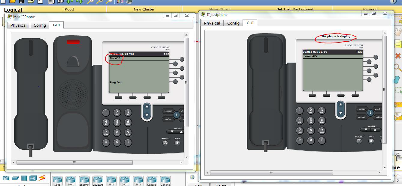 |
| Figure 3. Both phones are able to call each other. |
Here are some pictures from the actual hardware setup following this tutorial.
 |
| Figure 4. The actual IP phones may need a bit of tweaking to set them up. This is phone 1 in E50 building. Ext# 1111 |
 |
| Figure 5. The phone in the other building SPBA. Ext#2222. Calls were successfully made between the two buildings. LAN was bridged using Engenius (ENH202) devices. |


Basic Idea: To extend the LAN in the SPBA building to the E50 building using P2P Bridge (WDS mode) and also get voice and data services running. Worked out well.
Support my work by following me on this blog or my Youtube Channel. To download the completed Packet Tracer file for this tutorial. Click on download below. Let me know if you want me to create a follow up tutorial on this.
Great article, Thanks for sharing good and knowledgeable information. voip companies
ReplyDelete